Machine shops coming up to speed are asking the question, "What is CAD-CAM software?" CAD-CAM technology is the culmination of decades of contributions by many in the name of manufacturing automation. It is the vision of innovators and inventors, mathematicians and machinists the like, all striving to shape the future and drive manufacturing through technology. The term "CAD-CAM" is generally used to describe the software that is used for design and machining or manufacturing with a CNC Machine. CAD is an acronym for Computer Aided Design and CAM is an acronym for Computer Aided Manufacturing. CAD software is used to create things by designing and drawing using geometric shapes to construct a model. However not all manufactured parts have to be designed as a solid 3d model.
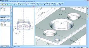
 Part shapes in CAD can be drawn using wire-frame geometry such as points, lines and circles, often to create 2d part shapes for machining. Generally CAD design software will allow the creation of surfaces; 3d contours that define the shape and can then be used in CAM for the CNC machine process. Modern CAD software allows for the creation of parts that are used in 2, 3, 4 & 5 Axis CNC machining. Therefore, CAD software is a necessary part of the manufacturing process as designed parts are transferred to CAM for programming the machine side of the manufacturing process.
Again, The term "CAM" is generally used in manufacturing to define the Computer Aided Manufacturing or Machining process. This is after a CAD design has been completed and CAM is needed to actually process the CAD part into a usable machine language that can be used by a milling machine or a lathe for machining. The language is often referred to as "G-Code". Before a CAD model can be turned into this machine language, the CAM software must be programmed in order to calculate cutting paths in which the tools that are being used will take to remove excess material and produce a part. Most often found in CNC Milling, CNC Lathe and CNC Router. Yet also found in the part programming process for CNC Water Jets, Plasma, Laser and CNC Burning machines.
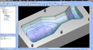
 The CAM software must determine where these tools will need to cut and at what cutting feeds and speeds. CAM software allows an operator to input tool data or select tools from a library within the software, manage and choose materials and create optimized "toolpath" for machining the designated CAD part model. The subjects revolving around CAD-CAM Toolpath are vast as there are many styles of toolpath that are used in a variety of machining circumstances. However, you typically will have Hole Drilling, 2D Toolpaths and 3D toolpaths that are available for use by programmers. These toolpaths include, profiling, pocketing, facing, engraving, 3d contouring and others.
There are many different types on CNC machines that are used in manufacturing. Major machine brands include Haas, Hurco, Fadal, Bridgeport, Mori Seiki, Fanuc and many others. Manual machines can also be retrofitted and turned into CNC machines by adding motors, CNC controllers and other important elements. The CAM software translates the machine toolpath and all of the other information through what is called a "Post Processor" in order to create an exact style of NC Code that the specific machine tool will understand. These post processors are often times customizable by the operator or a CAD-CAM technician. In either case, they are a necessary part of the CNC machine programming process.
BobCAD-CAM software is a complete CAD-CAM product that is used for importing and drawing 2d and 3d parts as well as generating machine toolpath and G-Code programs for 2, 3, 4 & 5 Axis CNC machining. Modules are also available for 2 Axis CNC Lathe as well as 2 & 4 Axis Wire EDM. The Milling software is also compatible with CNC Routers, Water Jets, Lasers, Plasma and Burning machine programming as the post processors are fully configurable for the other machines through posting.
For more information on CAD-CAM software please contact BobCAD-CAM today at 877-262-2231 or 727-442-3554.

